
abatec · Fibre optic technology
OTDR launch boxes and fibre test accessories
This category contains OTDR launch boxes for singlemode and multimode test setups. Match fibre type, length, connectors A and B, polish and design to the instrument and fibre under test.
Singlemode
G652.D and G657.A2: match the fibre specification to the fibre under test.
Multimode
OM1, OM2 and OM3: choose compatible fibre for the test setup.
Products at a glance
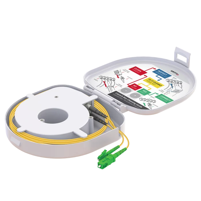

Part number: MT13262
net excl. VAT
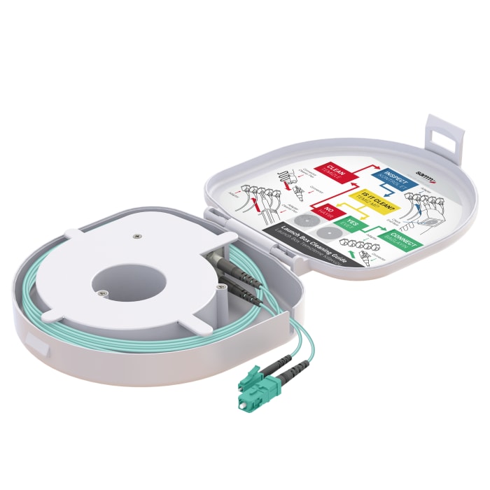

Part number: MT14347
net excl. VAT

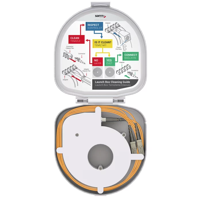
Part number: MT09948
net excl. VAT


Part number: MT13244
net excl. VAT


Part number: MT12828
net excl. VAT
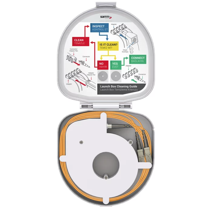

Part number: MT09947
net excl. VAT
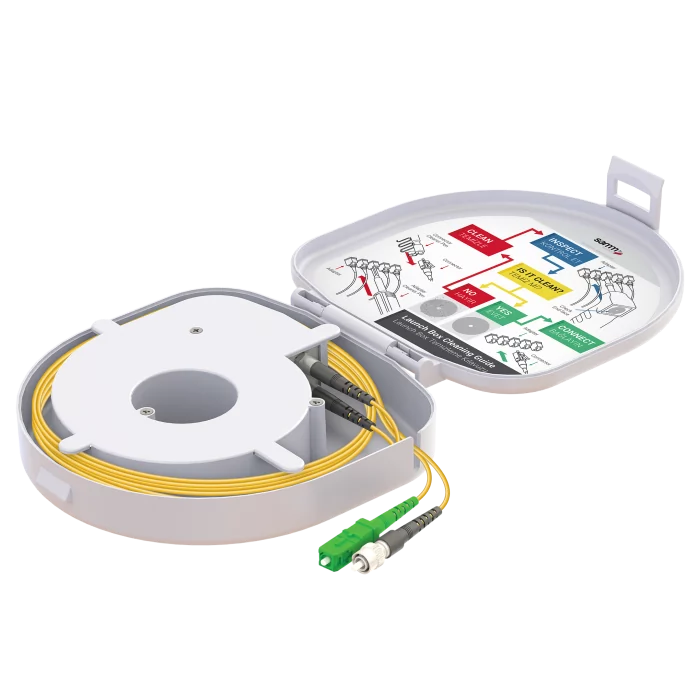

Part number: MT13603
net excl. VAT
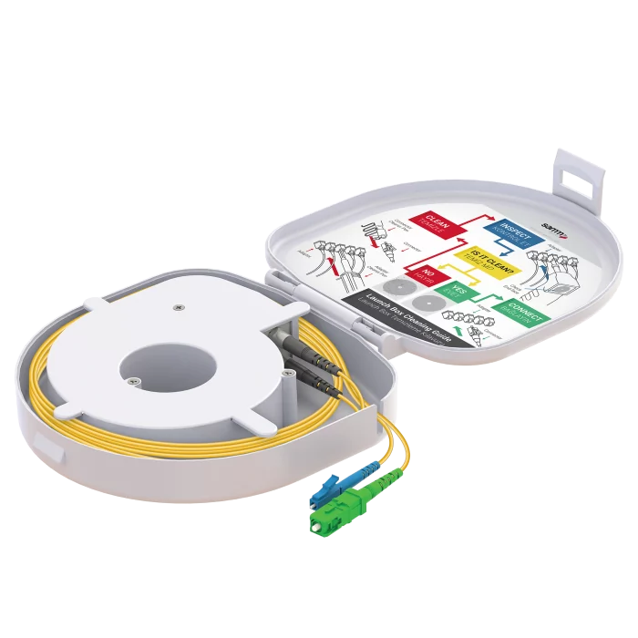

Part number: MT13263
net excl. VAT
Find the right solution for your application
Need help choosing a product or a tailored quotation? We provide personal technical advice.
- Quality
- Speed
- Reliability
- Flexibility


Part number: MT09949
- Fibre type:
- G651.OM3 · 50/125 µm
- Length:
- 150 m
- Connector A / B:
- SC/UPC / SC/UPC
- Design:
- Through type
net excl. VAT
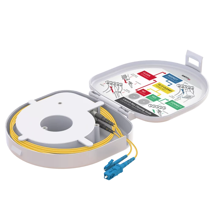

Part number: MT12587
net excl. VAT


Part number: MT13245
net excl. VAT
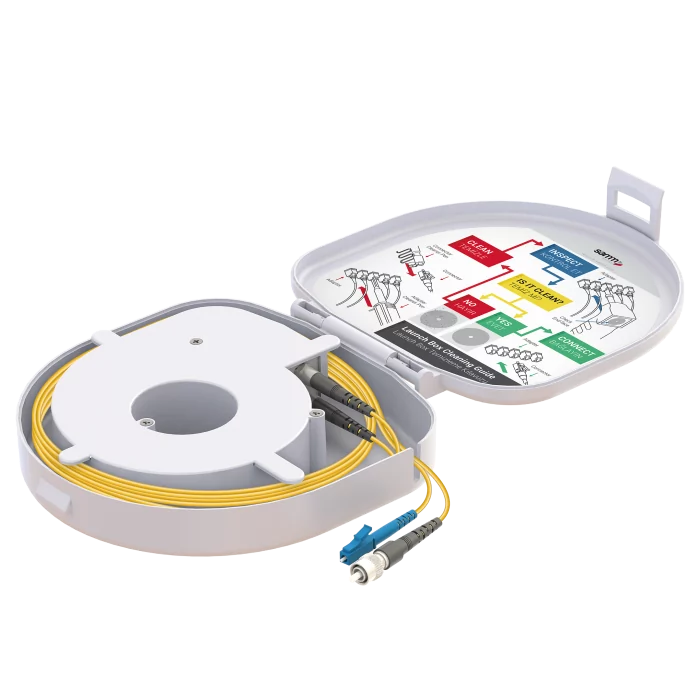

Part number: MT12650
net excl. VAT


Part number: MT13254
net excl. VAT


Part number: MT12795
net excl. VAT


Part number: MT12651
net excl. VAT

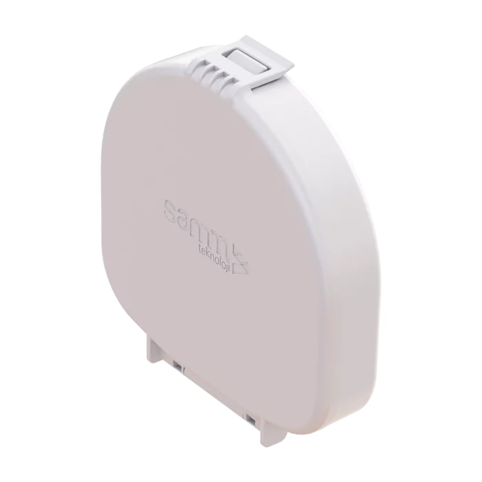
Part number: MT09942
net excl. VAT
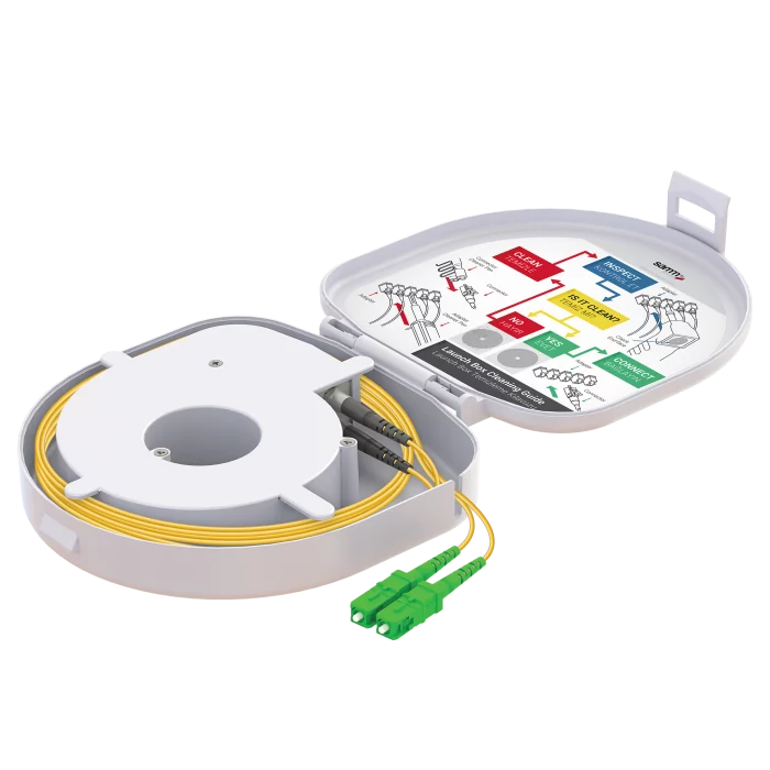

Part number: MT12280
- Fibre type:
- Singlemode G657.A2
- Length:
- 500 m
- Connector A / B:
- SC/APC / SC/APC
- Design:
- Through type
net excl. VAT


Part number: MT12652
net excl. VAT


Part number: MT12663
net excl. VAT


Part number: MT13250
net excl. VAT


Part number: MT09939
net excl. VAT


Part number: MT09941
net excl. VAT


Part number: MT09940
net excl. VAT


Part number: MT09944
net excl. VAT

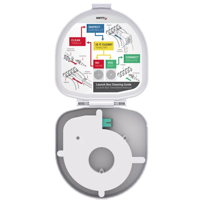
Part number: MT09946
- Fibre type:
- G651.OM3
- Length:
- 150 m
- Connector A / B:
- SC/UPC / SC/UPC
- Design:
- Adapter type
net excl. VAT


Part number: MT09819
net excl. VAT
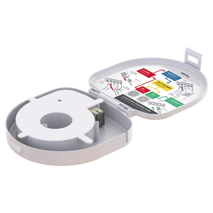

Part number: MT09945
net excl. VAT
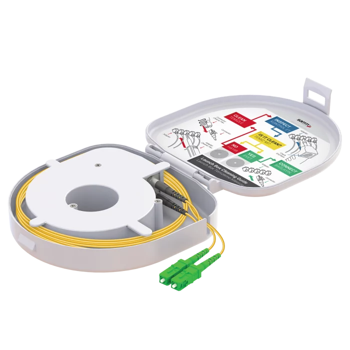

Part number: MT13023
net excl. VAT


Part number: MT13022
net excl. VAT


Part number: MT14922
net excl. VAT
Choose a launch fibre for your test setup
Define the measurement task first
The instrument and accessory combination depends on the required result. An OTDR analyses optical backscatter and locates events along the fibre. Range, wavelength and settings must match the fibre under test. Insertion loss measurement instead assesses the total loss of a connection.
Visual checks and connector inspection complement testing
A red light source or Visual Fault Locator (VFL) supports basic continuity checks and visible fault finding. End-face inspection shows contamination or damage on accessible connector surfaces. Neither method replaces OTDR or insertion loss testing, nor provides the corresponding quantitative assessment of a fibre route.
Fibre type and length
Transmission mode and fibre specification must match the instrument and fibre under test. The required launch fibre length depends on the instrument dead zones, measurement settings and intended event assessment. There is no universally suitable length.
Check connectors A and B separately
Check SC, LC or FC and UPC or APC on each side. UPC and APC must not be mated directly. Select through or adapter types based on the product details and intended handling.
Launch and receive fibres
A launch fibre provides fibre before the first connection. A receive fibre enables assessment of the final connection. Launch boxes do not replace an OTDR. OTDR event analysis and insertion loss measurement address different measurement questions.
Compatibility of the complete test setup
Consider wavelength, instrument interface, test cords, adapters and fibre under test together. Check both connector ends separately, including mixed connector combinations. abatec draws on many years of field experience with its own test equipment to support technical selection and offers insertion loss and OTDR testing services.
Related solutions and technical resources
- OTDR instrument selection (German)
- Insertion loss test sets (German)
- Insertion loss and OTDR testing services (German)
Frequently asked questions
What equipment is needed for an OTDR test?
An OTDR suitable for the fibre and measurement task, compatible test cords and, depending on the objective, launch and receive fibres. Wavelength, settings and connector interfaces must match the setup.
What does a launch fibre do?
It provides a defined length before the first connection of the fibre under test so that this connection can be assessed outside the relevant dead zone. Length depends on the instrument and settings.
Which launch fibre fits singlemode or multimode?
Transmission mode and specific fibre specification must match the instrument, wavelength and fibre under test. Also check both connector interfaces.
What is the difference between UPC and APC?
The connector end-face polish geometry differs. Match connectors, adapters and mating interfaces; the same connector shape does not automatically ensure compatibility. Do not mate UPC and APC directly.
When do I need launch and receive fibres?
The launch fibre precedes the fibre under test; a receive fibre at the far end enables assessment of the final connection. Required components depend on the test objective and specification.
Does an OTDR test replace insertion loss testing?
No. An OTDR analyses events along the route; insertion loss testing assesses the total connection loss. Required methods depend on the result needed.
What length do I need?
The length depends on the OTDR, measurement settings and test objective. Confirm these before selection.
Can a box serve as a receive fibre?
According to its product information, the OM3 through-type box MT09949 shown is also intended for use as a receive fibre. Suitability of other models must be checked separately.
Does this listing include OTDR instruments?
This listing currently contains launch boxes. These are test setup accessories, not measuring instruments.
Confirm the test setup and connectors
Specify the OTDR model, fibre type, measurement wavelength, required length and both connector interfaces.